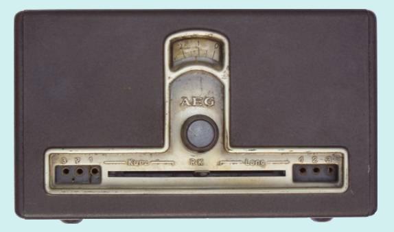
This German radio, originating from 1931/1932, was a gift
from a radiofriend (thanks Ed) who "rescued" it at an environmental depot in a
small town in the south of The Netherlands, close to the Belgian and German border.
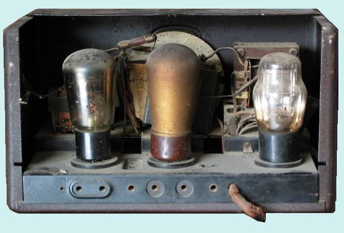
The capacitor box in the middle of the chassis was burst open and a resistor of 10 kohm in the power line turned out to have an infinite resistance.
Most components were significantly deviating from their original values. The mains wire was cut off, the handle of the on/off swith was broken and the combined upper/back cover was gone.
All tubes (REN904, RE134 or RES164 and RGN354) appeared to be OK, however, one of the pens of the RGN354 was broken off.
In my case an A4110 (an equivalent of the REN904) was mounted at the
position of the REN904.
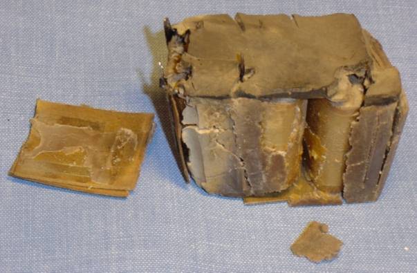
I removed the "exploded" capacitor box, output
transformer and tuning dial and cleaned the chassis.
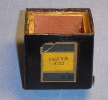
The content of the capacitor box was removed and the box was refurbished and
strengthened with a wooden structure.
Three new capacitors were mounted in the interior and the remaining room partly
filled up with tissue. The original black tar was molten and the melt used to
seal the box.
A new cloth covered cord with connector was mounted and the open circuit resistor replaced. The damaged base of the tube RGN354 was replaced by an undamaged one. The broken handle of the on/off swith was glued with 10 seconds glue, using a small ring for reinforcing the delicate construction.
I decided not to replace the components having values
quite different from the original ones (e.g. 1.35 vs. 1 Mohm, 279 vs. 200 kohm,
1768 nF vs. 1000 cm).
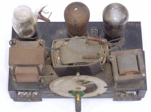

chassis before restoration
chassis after restoration
Schematic
The letter "W" in the model name 201W refers to "Wechselstrom" (= AC =
alternating current). An earlier model is the 201G where the letter "G" refers
to "Gleichstrom" (= DC = direct current). Obviously no schematic of the Geadux
201W is available on the Internet or in other databases. The schematic of the
model 201G, however, as well as a 201W version made by converting a 201G, can be
found at various sources (a.o. in "Empfänger-Schaltungen der Radio-Industrie"
von Lange und Nowisch, Band I, 3rd edition, 1952, p. 110-111).
As a result I have drawn up the schematic of my Geadux 201W myself. The schematic appears to be different from the schematic of the converted 201G in some details.
In the first place there are minor differences in the power supply, especially because model 201W is using tubes (REN904 and RE134) with other heater voltages and construction than the tubes in model 201G (REN1821 and REN1822).
Finally the mass of my 201W is directly connected to ground. For that reason two capacitors which are present in model 201G (values 1 nF and 50 nF, in the antenna coil section) are not present in my radio.
The schematic can be viewed here: schematic AEG Geadux
201W.
As I was not able to determine the values of he three capacitors in the
"exploded" box, I have indicated them in the schematic with the notation C1, C2
and C3.
I connected an external speaker with an impedance of about 1 kohm (I do not know what the recommended speaker impedance is here) and several Dutch, German, Belgian and other stations could be heard. During tuning it is necessary to "play" with the handle of the reaction control.
The combined upper/back cover is still missing. If I would have a proper drawing or picture of it available, I could try to reconstruct this cover.
In my opinion the design and lay-out of this radio are rather special. On the upperside of the chassis no coils are mounted. There are only quite tiny coils under the chassis. The handle for the reaction control is moving the coil in the anode circuit of the REN904 and activates a switch (in the antenna coil section) in the most right position.
In case the tube RE134 is replaced by a RES164, a connector on the chassis upperside
(between the two tubes on the right hand side of the picture above) has to
be used to make a link to the additional grid of the RES164.
|