The Orion 115A originates from 1950
(Hungary). It has no tuning capacitor, but can be switched to 3
fixed frequencies.
During some years after WW II only two MW stations were available
in Hungary: Budapest 1 (Kossuth) and Budapest 2 (Petöfi). On
places where reception was weak, use could be made of a relay
station. This explains the 3 positions on the frequency switch.
The receiver is housed in a simple wooden cabinet.
Tubes employed: UCH21, UBL21, UF21, UY1N.
Model 115A has a "brother", model 115B, employing
battery tubes.
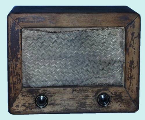
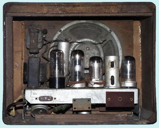
I bought the Orion 115A in an antique shop
in Keszthely, a town west of the Balaton lake in Hungary.
A visual inspection did not reveal damage to electronic
components and after having carefully charged the smoothing
electrolytic capacitors, 220 Volt was supplied (in steps).
Thereafter local stations could be heard on all three positions
of the frequency switch.
As can be seen from the picture of the front, the radio needed
quite some restoration. Apart from a damaged grille cloth and
cabinet, the interior demanded further attention.
By the way, the original knobs were missing. I replaced them
initially by knobs from my junk box.
In front of the grille cloth a horizontal wooden bar was missing
too.
In the meantime this Orion has been restored. Although the radio
played pretty well, I decided to dismantle it until the last
screw and piece of wire. This seemed to me the only way to clean
the chassis and components.
 |
This picture shows all components after
dismantling, except for the tubes. In order not to damage
the six delicate RF and oscillator coils they were put in
protective plastic bags. All pieces of wire were tagged with a
label, so enabling me to put them back on their original
place.
|
Apart from the cleaning operation, I
replaced the smoothing (electrolytic) capacitor, as it turned out
to be rather leaky. The antenna series paper capacitor showed a
short-circuit. For security's sake also all other paper
capacitors were replaced. This was accomplished by emptying the
respective housings, placing new high quality components in the
original housings and sealing them again with a dark grey,
kneadable two-component epoxy. This material hardened after 5 to
10 minutes after mixing the two components by kneading.
After remounting all cleaned parts on the cleaned chassis and
supplying 220 Volts, the speaker confirmed that there was life in
the equipment again. I first checked and corrected the aligment
of the IF by supplying a modulated 473 kHz signal to grid g1 of
the mixer UCH21. Then the main oscillator coil (middle position
of channel switch) was set at a strong local (Belgian) station on
the lowest side of the band. In the left and right position of
the channel switch other coils are switched parallel to the main
coil, so lowering the inductance of the combination and resulting
in a higher resonance frequency. I set these coils to the
frequency of two other strong local (Dutch) stations. Finally the
RF coils were peaked.
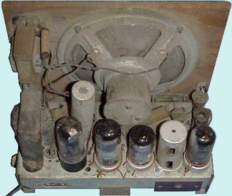
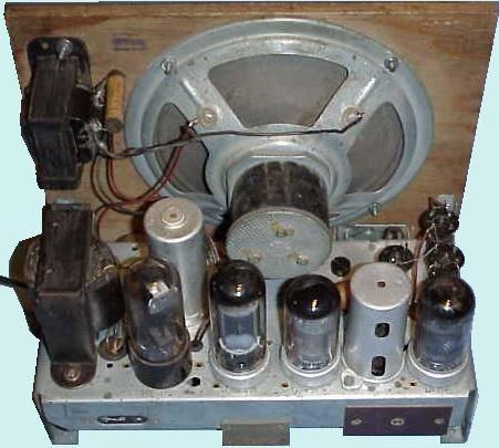
| Chassis before restoration |
Chassis after cleaning and restoration |
The cabinet was soaked in hot water for a
short while. Thereafter the glue weakened and the front and side
panels could be taken apart. The dried parts were cleaned and
glued together with a polyurethane wood glue. The cabinet was
painted with a transparant middle oak acrylic coating and
finished with a protective transparant coating.
The backpanel was cracked and folded. By placing it a for a few
weeks under a heavy load press it got its original structure
again, more or less. Final step was refurbishing of the imprinted
gold coloured text, symbols and drawing on the backpanel.
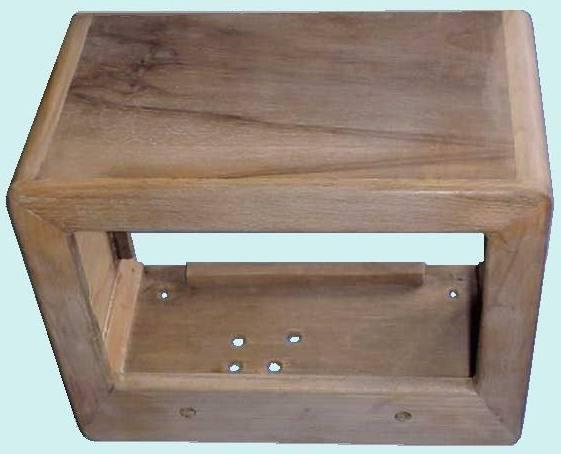


Remounted cabinet
Finished radio
Refurbished back panel
A kind Hungarian collector, living in
Austria, was so kind as to provide me with the missing wooden
bar, a replacing grille cloth and the missing knobs. |


